ECE 4160 Fast Robots
Raphael Fortuna
Lab reports made by Raphael Fortuna @ rafCodes Hosted on GitHub Pages — Theme by mattgraham
Home
Lab 4: IMU
Summary
In this lab, I added the inertial measurement unit (IMU) to the Artemis code stack and transmitted IMU and ToF via BLE. I also soldered a JST connector to one of the battery packs that we received with the RC car and used it to power the Artemis. The Artemis was then attached to the car with the IMU and ToF sensors and sent data while it was driving.
IMU Setup Task
I first installed the SparkFun 9DOF IMU Breakout - ICM 20948 library and then connected the Artemis to the IMU and loaded the Example1_Basics example from the installed library. It ran correctly and its output is shown below.
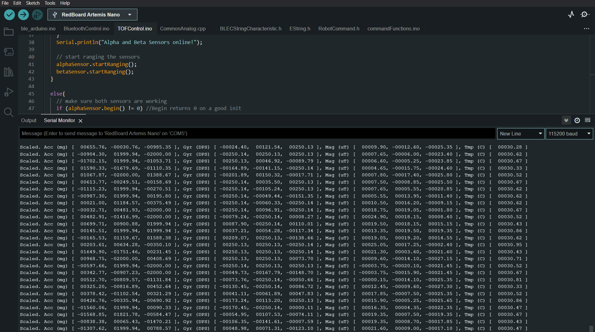
The code featured a AD0_VAL definition set to 1 since the ADR jumper was not closed on the IMU. This is the default value as per the example code and is correct since I did not solder the jumper closed.
When moving the IMU around, I found that the acceleration only changed with movement and rotation and became jittery with fast changes. It also had the pull of gravity present in one of the axes.
I found that the gyroscope values changed mainly with rotation and did not have the pull of gravity affecting its values.
Visual Indicator Task
I added a visual indicator to blink the LED 3 times once the setup was complete for the Artemis to show everything is running. I made it so any number of blinks could be shown so it could be reused elsewhere.
Accelerometer Task
I used the IMU lecture's sample code and directions as a basis for my accelerometer pitch and roll calculations.
I used these equations for pitch and roll:
Pitch: θ = atan2(x_acceleration , z_acceleration)
Roll: 𝜙 = atan2(y_acceleration, z_acceleration)
Here is a video with each output of the accelerometer for -90, 0, and 90 for pitch and roll.
Pitch:
Roll:
When measuring the accuracy with a two-point calibration, I found that it was pretty accurate, with 180 degrees being measured as 87 and -91 degrees for a combined 178 degrees. The conversion factor for this is 180/178 = 1.011; however, I will not be using since the +/- sides have different errors.
Accelerometer Noise Task
I ran the car above the accelerometer to see how much its value changed and sent 20 seconds of data to my laptop using a new command that collected and sent 5 seconds worth of accelerometer data. After gathering this data, I split up the pitch and roll data and ran a FFT on the data using the tutorial found here. The graphs generated are below.
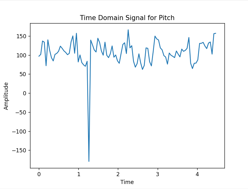
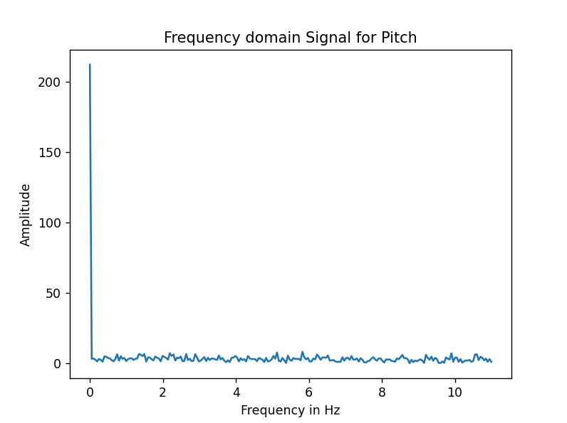
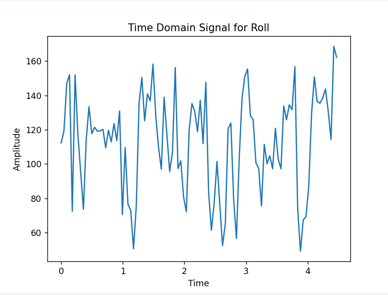
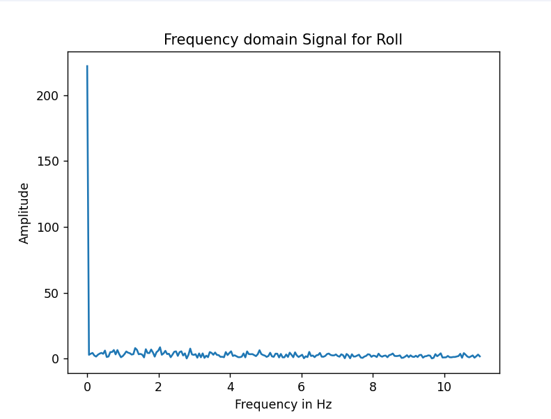
In both the pitch and roll, the frequency found was under .1 Hz. This was because the chip already had the low noise mode set as default for the accelerometer as discussed in the accelerometer noise performance table found on page 12 of the datasheet found here. So, a low pass filter is not needed for the accelerometer.
Gyroscope Task
The equations I used were:
Pitch: θ = θ_old - gyroscope_x*dt
Roll: 𝜙 = 𝜙_old + gyroscope_z*dt
Yaw: ψ = ψ _old - gyroscope_y *dt
These matched both with the accelerometer directions and with the airplane diagram given in class.
At high sampling frequencies, with a delay of 10 milliseconds or less, the gyroscope and accelerometer largely matched when moving the IMU slowly, but fast jerky movements could cause the error to build up quickly in the gyroscope. This error was even more substantial at lower frequencies, with at one point getting into the mid-thousands when moving the IMU too fast, while the accelerometer was less affected.
The direction of the yaw and pitch value from the gyroscope also had to be flipped to match that of the airplane diagram.
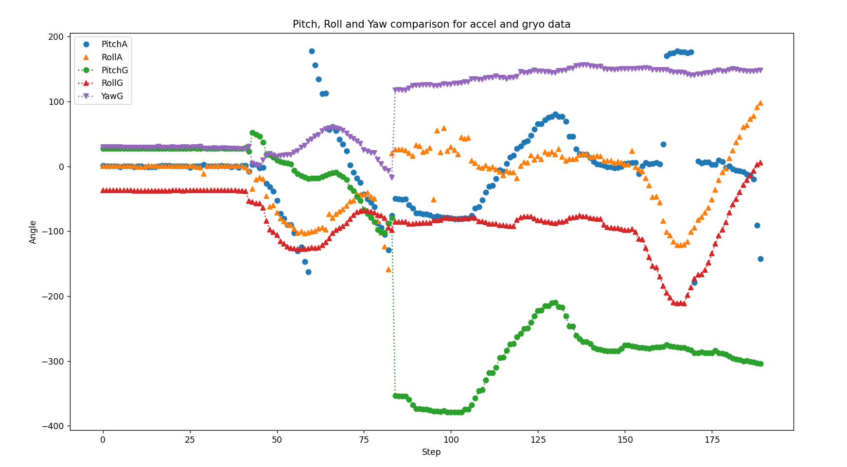
When collecting data, the data initially matched, but when time when on, the gyroscope values built up a lot of error and deviated from the accelerometer.
Complimentary Filter Task
The range is +/- 90 degrees for the roll and pitch and as seen in the video below, it is not susceptible to drift or quick vibrations. I used 90% of the gyroscope and 10% of the accelerometer with a delay of 1 millisecond per loop.
Sample Data Task
I used the functions I created before to get the gyroscope and accelerometer values as well as the complementary filter values and placed them in their own file with an initialization called in my setup. By using this and a test function, I was able to sample new values every 8 milliseconds, so 125 times per second.
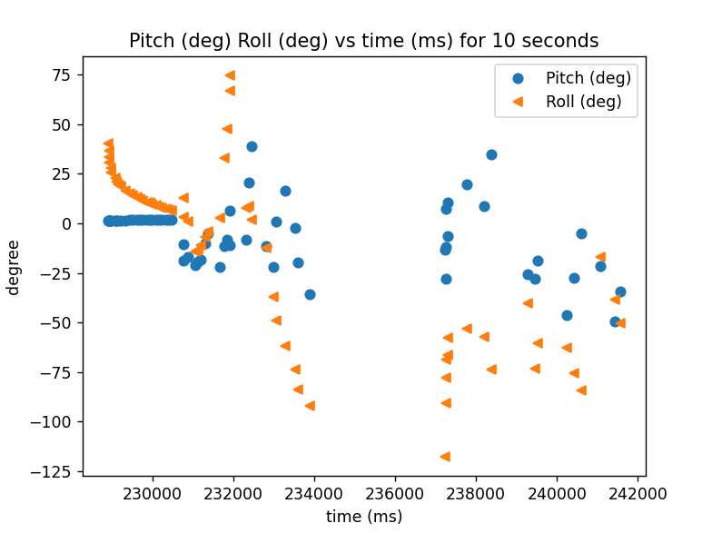
I transmitted pairs of the complementary data to the laptop using Bluetooth and processed them into their own arrays of pitch and roll as seen in the graph below.
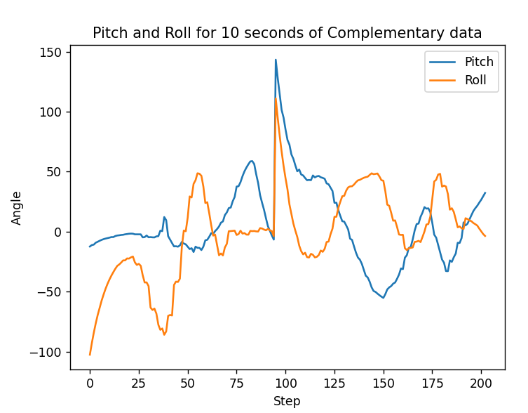
If one big array is used to collect the data on the Artemis, this means that more processing needs to be done by the Python code. If instead two separate arrays are made, this means that it would be easier to process, but the data could be out of sync since either ToF or IMU data could have arrived before or after the other repeatedly due to differing update times.
I will use two arrays because of the very different updates times for each sensor and the simplify data processing. I added a new UUID for each array being sent to my laptop as a different characteristic in the service.
The amount of memory available for arrays is 393216 bytes from the Arduino IDE assuming no other local variables or overhead. Since time values are 4 bytes and floats are 4 bytes, this means for each pair 8 bytes are needed.
The ToF sensors update every 102 milliseconds, meaning just under 10 values per-second, while the fastest the complementary filter data could be sampled at was 8 milliseconds, meaning 125 values per-second. So, ToF sensors require at most 80 bytes per-second and IMU data requires 1000 bytes per-second, for a combined 1080 bytes per-second. This means data can be stored for 393216 bytes /1080 bytes/second = 364 seconds.
Data Recording Task
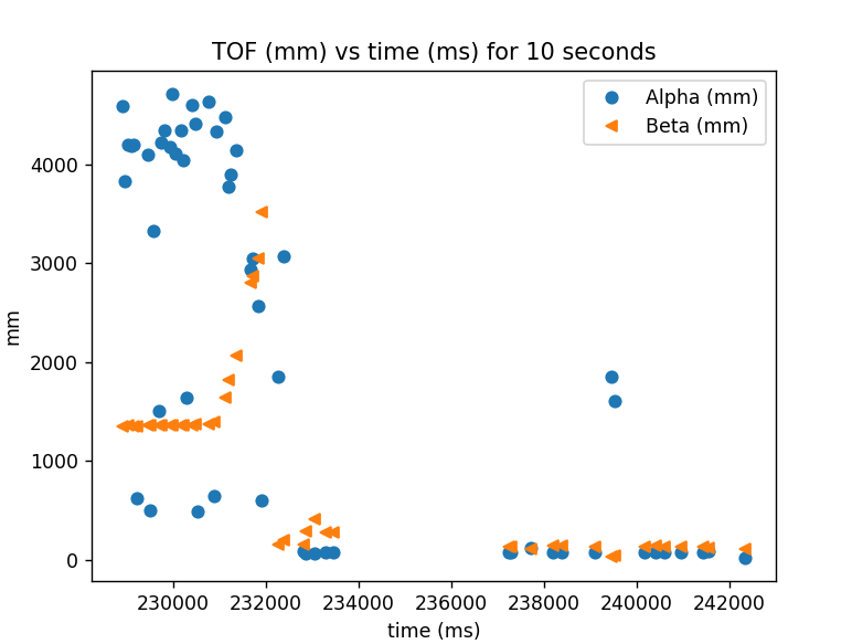
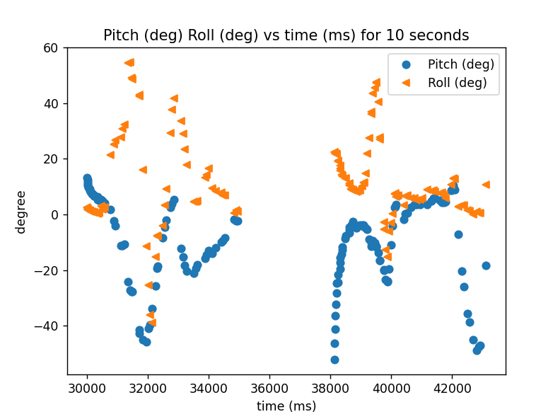
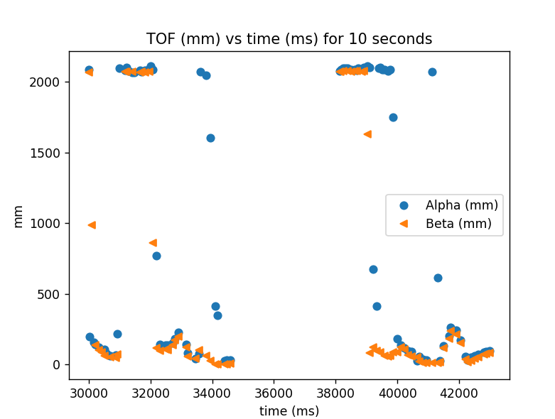
I created a test function to send data over to my laptop and processed the data to show the outputs on a time series graph. I updated my code to have two new characteristics and for all code handling BLE to now take in a reference to the characteristic objects to simplify the code for any future characteristics.
Here is the new IMU processing function that compliments the previous ToF processing function.
Battery Task
I cut each wire of battery one at a time and soldered it to the 2mm JST connector and used heat shrink to protect each connection. The larger battery is being used for the motors since it has 200 more mAh to let more tests be done at one time.
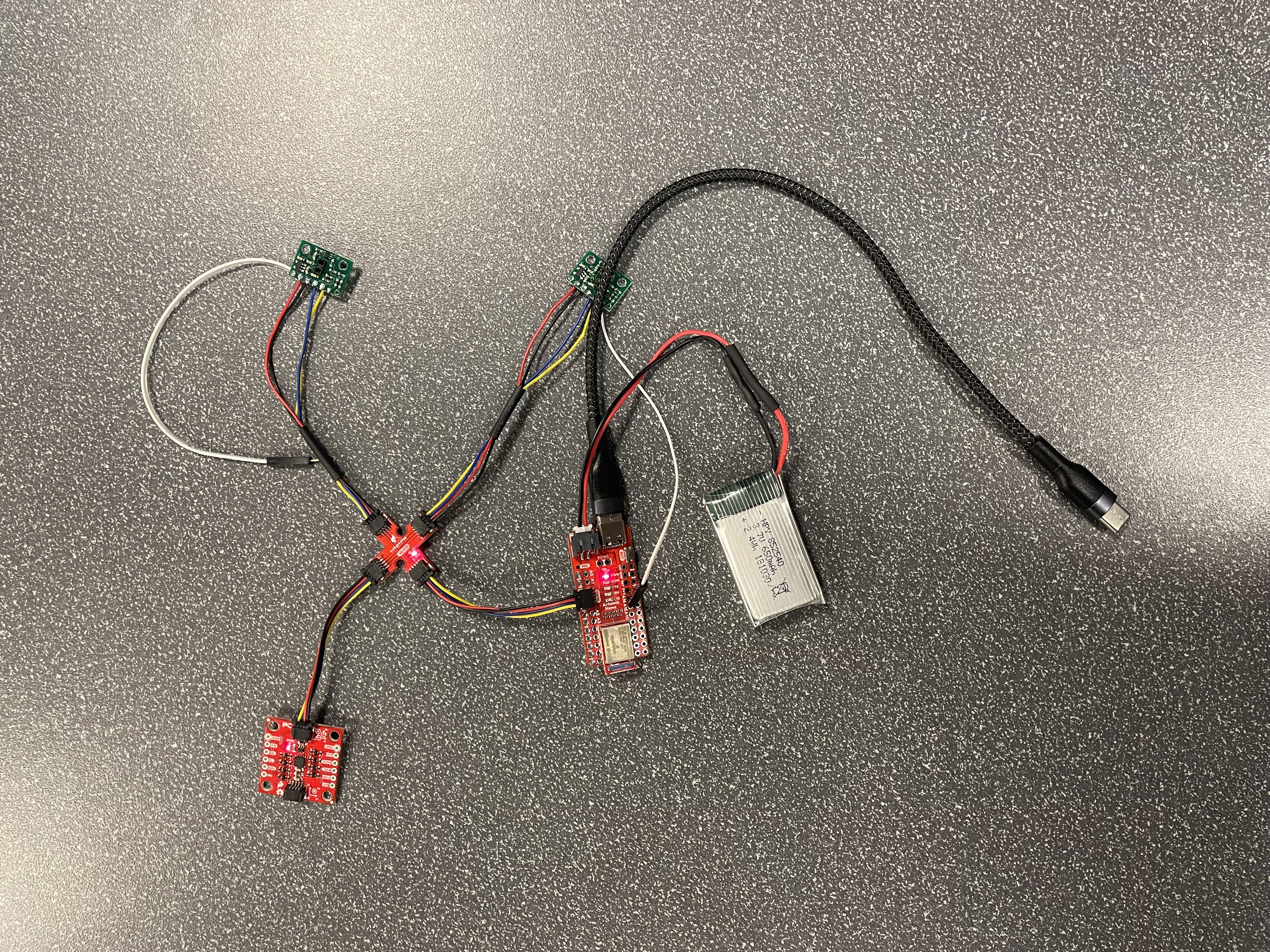
I charged the battery pack using the board and was able to send sample data via Bluetooth and also saw the LED blinking to show the board setup correctly.
Stunt Task
I plugged in the 850mAh battery into the car, taking the polarity into consideration and drove it around as seen below.
I found that the car is very fast, sensitive to inputs, and difficult to control. Turning led to the car spinning in a circle and reversing direction suddenly caused the car to flip.
Artemis Stunt Task
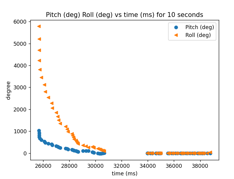
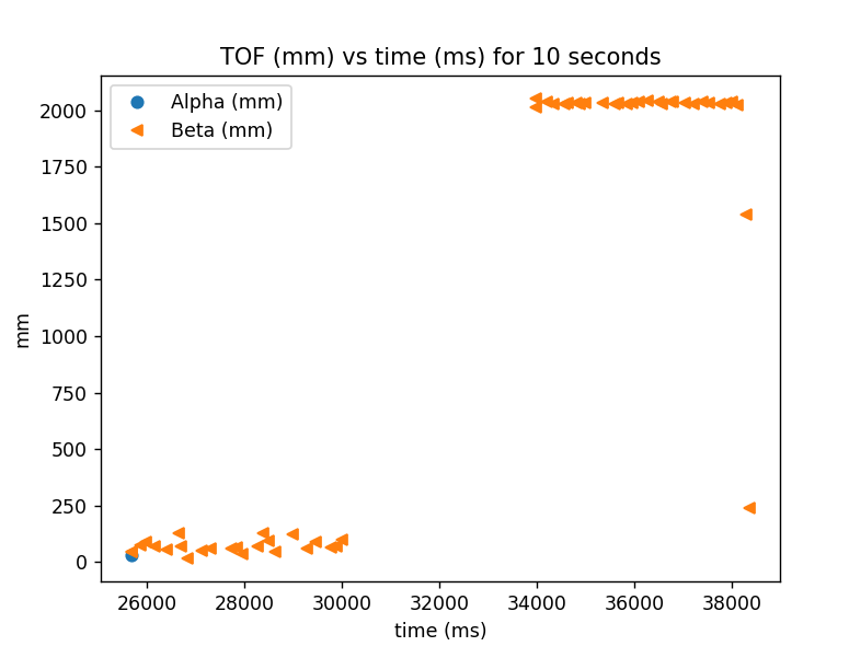
I mounted the Artemis and battery to the car, taking care to make sure neither would fly off and recorded the video and data shown below. I sent and processed the data using the same commands and functions as before. The same behavior was noticed as in the previous task.
